News
One container, five facilities: an SSRL tomography workflow at SC26
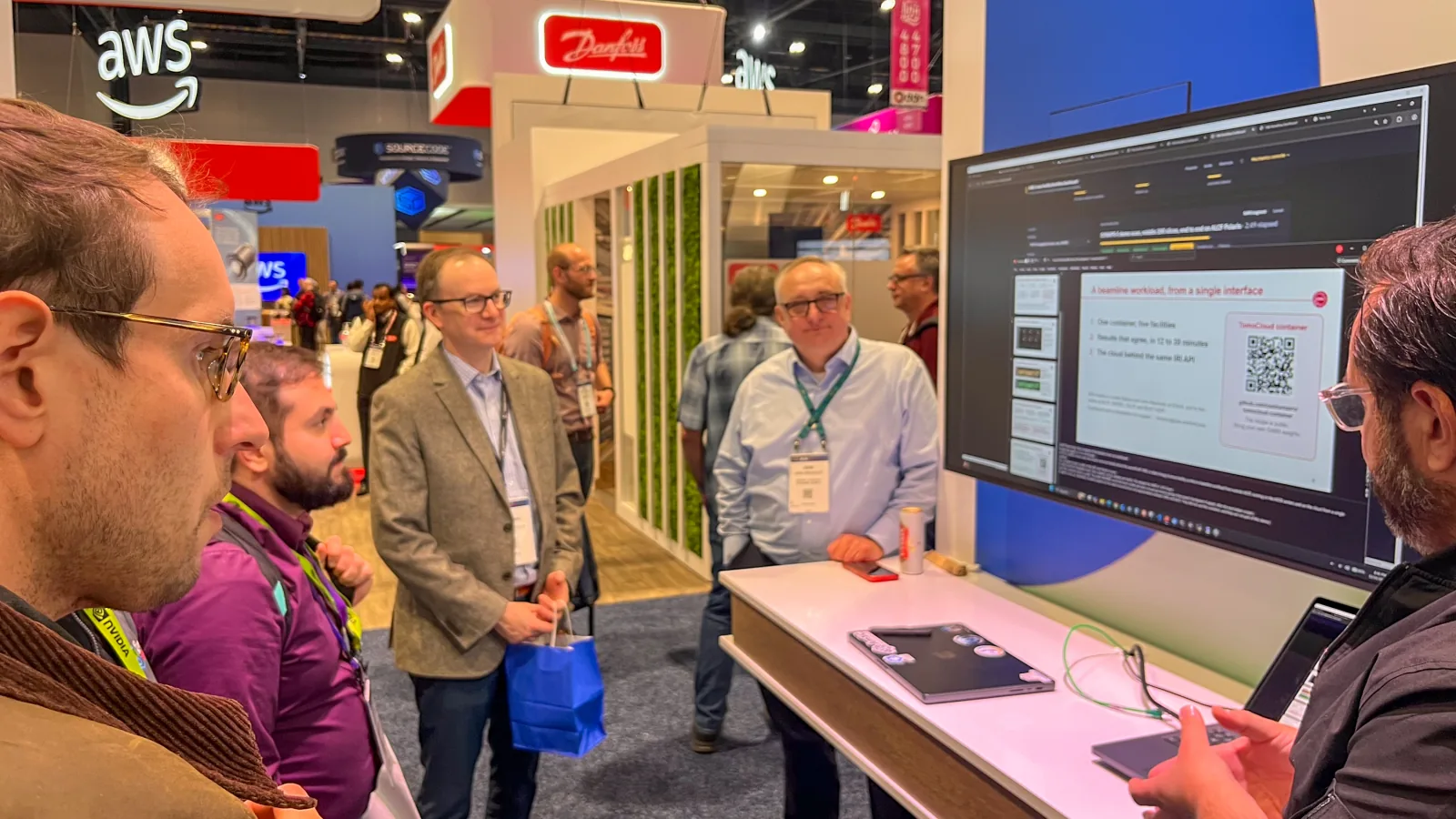
At SC26, an X-ray tomography workflow from the Stanford Synchrotron Radiation Lightsource showed how one portable container can move among five computing facilities through a common IRI interface.
Tim J. Dunn of the Stanford Synchrotron Radiation Lightsource (SSRL) at SLAC National Accelerator Laboratory presented the beamline workload as the scientific-user half of ESnet on AWS: A Cloud Facility Behind the IRI API. The demonstration, developed with Justas Balcas and John MacAuley of ESnet, has two SC26 sessions at the Department of Energy booth in Chicago: November 16 at 8:00 p.m. and November 18 at 4:00 p.m. Central.
The broader American Science Cloud tomography workflow spans the Advanced Photon Source, the Advanced Light Source, and SSRL, and launches through IRI.
The campaign behind the presentation covered ALCF Polaris, NERSC Perlmutter, OLCF Defiant, SLAC S3DF, and an AWS environment operated by ESnet. Each recorded run was launched separately from the same dashboard, through the target facility’s IRI API.
From a scan to one portable container
The workload starts with X-ray microtomography data from an SSRL battery-cathode experiment. It uses tomocupy for GPU reconstruction, writes the volume and image pyramids in OME-Zarr, and applies the SAM3 segmentation model. A checkpoint fine-tuned for SSRL battery-cathode data under SYNAPS-I travels beside the TomoCloud container; the container itself holds the rest of the pipeline.
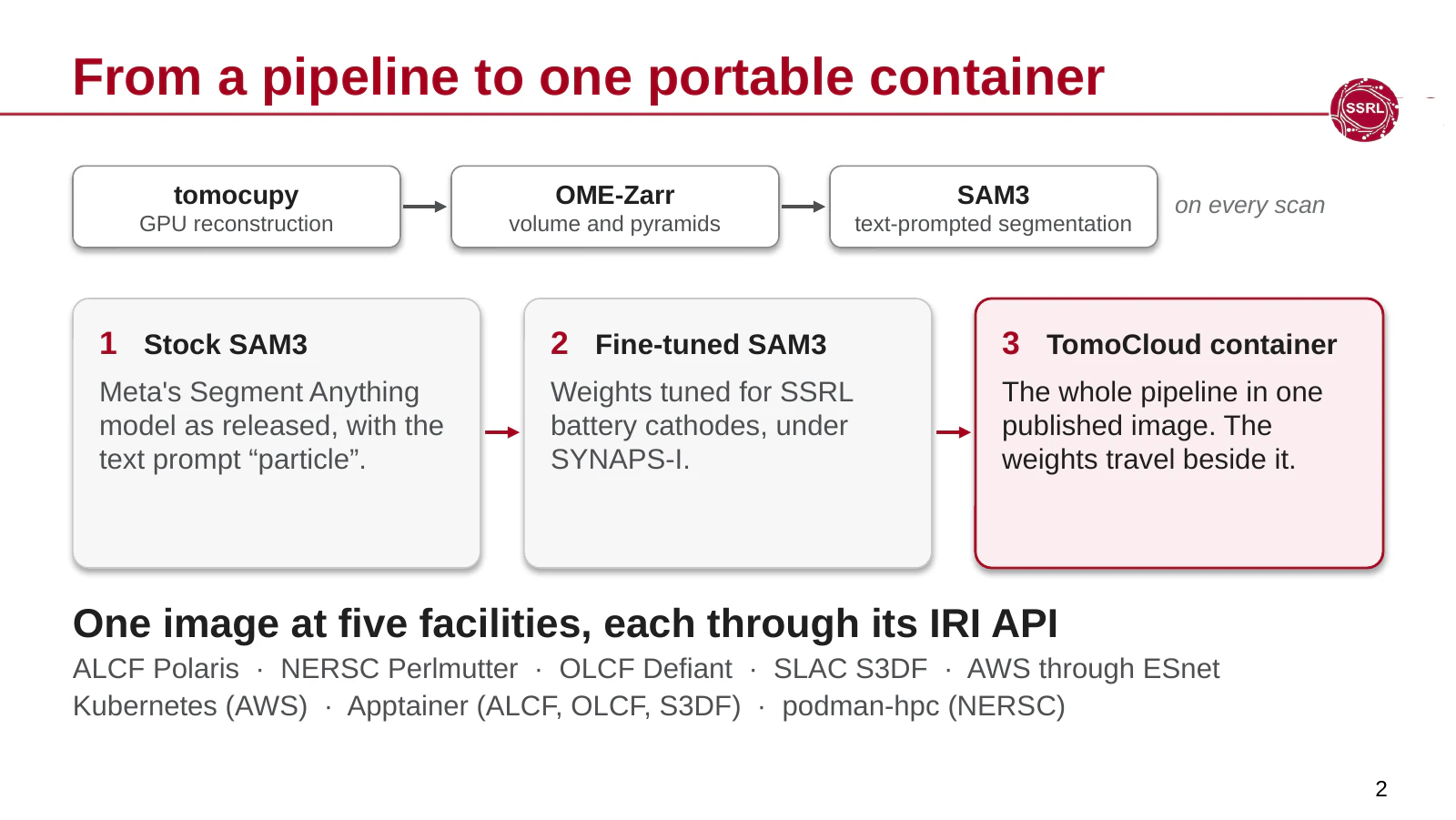
The container image ran under Kubernetes on AWS, Apptainer at ALCF, OLCF, and S3DF, and podman-hpc at NERSC. Those execution environments, along with local queues, storage, and policy, remained facility-specific. The dashboard’s adapter for each facility translated the common client operations for that site’s IRI API.
Five separate launches from one dashboard
For each run, the dashboard operator selected a scan, a facility, and a model, then followed the same seven workflow stages. The campaign used the same 2048-by-2048-by-2048-voxel scan and eight GPUs at each destination, but not identical hardware or queue configurations.
The demonstration tested whether the scientific workflow and interface could travel, not which facility was fastest. ALCF and NERSC used A100 GPUs, AWS used L4 GPUs, OLCF used H200 GPUs, and S3DF used L40S GPUs. The node counts, queues, and storage paths also differed.
Results that agree across facilities
The presentation compared the segmented volume from all five recorded runs. In slice 1054, 92.9 percent of the pixels labeled by any run were labeled by all five. Across the complete three-dimensional volume, the intersection over union for any pair of runs ranged from 0.9875 to 0.9889, where 1.0 would be a perfect match.
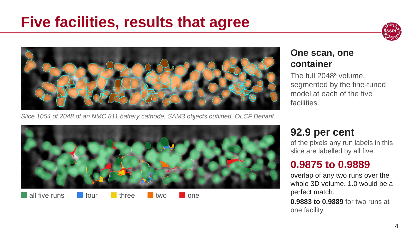
The 92.9 percent figure measures agreement, not scientific accuracy. In the slice shown, the differences sit in a few crowded spots where particles touch. Repeat runs at one facility varied by a similar amount, so most of the difference is run-to-run variation in the segmentation step, not a facility effect.
Turnaround on the scale of a sample cycle
The five campaign runs took 12 to 30 minutes from launch to completed result. That interval included queueing, input transfer where the scan was not already at the facility, computation, and bringing the results back to SSRL. It is comparable to the 20-to-30-minute sample cycle at SSRL beamline 6-2, giving scientists a route toward seeing one sample’s analysis while the next sample is on the stage.
Queue selection still mattered. An earlier run of the same job waited 42 minutes in a debug queue; the run used in the comparison waited 31 seconds in an express queue. The presentation treated these results as workflow timings, not a hardware benchmark, because the five facilities used different GPUs, queues, node counts, and storage systems.
Before this workflow, usable analysis could arrive weeks to months after beamtime once manual steps were included. The SC26 result is not a measured speedup against that older process. It shows that the reconstruction and segmentation path can be packaged, submitted, and returned on a timescale that is relevant during an experiment.
The cloud behind the same IRI API
From the user’s point of view, AWS through ESnet became one more facility behind the same IRI API. The local details did not disappear: a new workflow still needs a facility job script, and every provider retains its scheduler, execution environment, access controls, and operating policies. What became portable was the way the dashboard described, launched, monitored, and retrieved the work.
The TomoCloud container recipe is public. Read the earlier SC26 IRI demonstration preview for more about the ESnet AWS facility and IRI 2.0 demonstrations.